Let’s Start Work
Together
Please feel free to contact us. We will get back to you with 1-2 business days. Or just call us now.
Transformer Testing
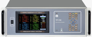
3 Phase Power Analyzer
It is widely used in Tramsformer No Load Test & Full Load Test. It is also used to test watt loss of Transformer builtup core. 3 Phase Power Analyzer is also used in Transforrmer Test bench.
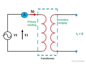
No Load Test-No-load tests are tests that apply rated voltage in the primary side at the no-load state of the secondary side. Current only flows to the primary side in the no-load test, but this current causes excitation and iron loss of the iron core.It is also called Open Circuit Test of Transformer
Full Load Test-The ammeter reading gives the primary equivalent of full load current IL. As the voltage applied for full load current in a short circuit test on the transformer is quite small compared to the rated primary voltage of the transformer, the core losses in the transformer can be taken as negligible here.It is also called Short Circuit Test of Transformer
Core Loss Test- Both short circuit and open circuit tests are conducted to measure the core and winding losses of transformers.As we know therer are mainly two major parts of transformers core and winding, which are made of two type of matrial i.e. iron & copper. The core of transformer is made of iron whereas the winding which is wrapped over the iron core is made up of copper.
3 Phase Power Analyzer

Tranformer Turns Ratio Meter
Turns Ratio Test-It is used to test the Turns Ratio of Transformer windings winding, It is measured from HT side winding to LT side winidng. Vecor Group & Polarity also determined by using the Transformer Turns Ratio Meter.
Transformer Turns Ratio testing is commonly used to ensure that the winding ratio between the primary and secondary coils are aligned to recommended specifications. This type of transformer testing also ensures the transformer will provide either step-up or step-down voltage. A step-down transformer, for instance, comprised of 100 primary turns and 10 secondary turns will work to reduce the voltage by a factor of 10 — corresponding to the secondary coil — while multiplying the current by 10 as well.
Turns Ratio Meter

Our Solutions & Benefits
We provide Transformer Testing Equipment, which is widely used in Tranformer Manufacturing & Service Industries. We provide better solution for better quality of Transformer Testing Equipment. Our Products are robust, reliable and easy to opearte.
No Load & Full Load Testing of Transformer
Used to measure turns ratio, polarity, vector group, deviation of transformer
Our single sheet tester & Epstein Tester could be used to test CRGO material quality.
FAQs
The purpose of load test is to determine the parallel operation and calculate the efficiency, thermal stability and dynamic stability of power transformer through measuring the short circuit loss and impedance voltage of power transformer.
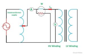
Open circuit test or no load test on a transformer is performed to determine 'no load loss (core loss)' and 'no load current I0'. Usually high voltage (HV) winding is kept open and the low voltage (LV) winding is connected to its normal supply.
While primary winding carries a small current I0 called no-load current which is 2 to 10% of the rated current. No-load current I0 is responsible for supplying the iron losses (hysteresis and eddy current losses) in the core and a very small amount of copper losses in the primary winding.


Switch on the supply and apply the rated voltage of secondary winding by varying the autotransformer. Note down the ammeter, voltmeter, and wattmeter reading for the no-load & full-load conditions. Switch on the load and apply the load in steps up to the rated secondary current.

